I took some shots of our well when I was up there last weekend. It sure looks like a nice little package and I’m looking forward to running it.

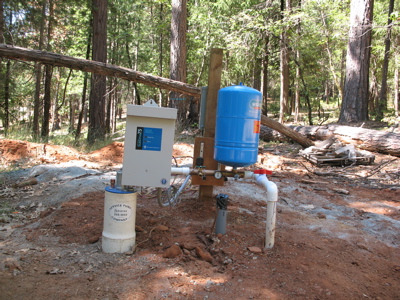
This is the “front” of the well. The motor/pump controller is on the left, the tank is the blue bit on the right and our electical box is on the other side of the post. The big white tube is the well itself and the little white pipe is our water supply line to the house. The small grey pipe is where the electrical will come out.

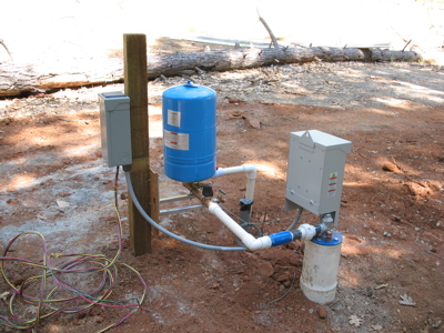
A side view – you can see the electrical box on the post now. The entire system is actually supported by some metal brackets hung off the post. Before we start getting weather this fall/winter, I’ll build a small structure around everything here to protect it.

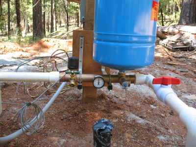
A closer view of some of the component bits. The black “knob” above the spigot is the pressure sensor. The gauge in the middle indicates the pressure and the red bit on the right is the ball valve (currently closed) which prevents the water from going into our supply line (which is wide open and would make quite a mess).

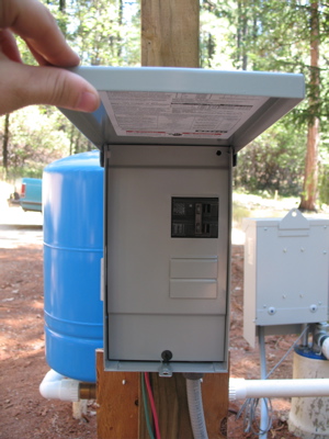
Instead of the usual cut off switch, I had the pump company install a small electrical box. This way, I have space for my breakers for the light and courtesy plug I’ll be installing in the future. The light will be hooked up to a thermostat and we’ll use it to keep the pump house from freezing during the winter.
