We took the opportunity of the long weekend and my Dad being in town to try to focus on the house. I got back into rough carpentry mode for a bit before putting my electrician and plumbing hats back on. I also got to try on a circus high wire hat – that’s one I don’t want to use again but I fear that I have no choice.
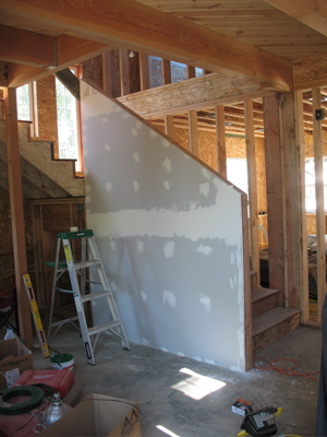
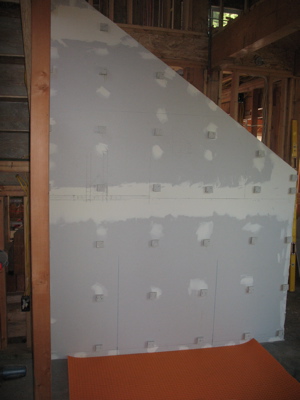
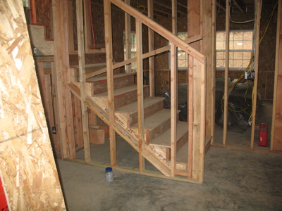
Since we’re putting a wood stove near our stairs, we need to build a wall behind it to protect the stairs from the heat and anyone from putting an arm through the stairs onto the stove. Instead of trying to mix a small protective wall with a banister and balusters we decided to just make a bigger wall and hang the banister off of it. We thought it would look better that way – less haphazard. I bought wood and cut it all on Friday. On Saturday, I assembled it and my Dad helped me put it in place and get it plumb. Sunday found me adding the fire blocks and yesterday, I pulled out the topmost fireblock to beef up the tallest stud into more of a corner so that there’s a place to mount the banister. It looks good, but I’m fairly out of practice at carpentry because it should have gone a lot faster than it did. I still need to get some OSB to take the wobble out of the lower end.
At one point, while take a break from carpentry, I went up and began manipulating the hot and cold water lines for the toilet and bath in the kids bathroom, attempting to force them through the holes in the stud and floor that I’d drilled for them previously. During the course of my wrestling, the cold water line came loose from the T that I (thought) I had crimped it to before I laboriously moved the tub into place. After examining the crimping ring (it’s PEX) I discovered that I had not in fact crimped it. I took apart the waste line plumbing (that I had just dry-fit, not glued) and proceeded to laboriously move the tub out of the way enough to get at the plumbing bits behind it so that I could check the other fittings to make sure they were crimped and fixed the one I disturbed. Now, I say “laboriously” because this is a cast iron tub which weights somewhere between 450 and 600 pounds depending on which literature or sales person you believe. The only way for me to move it by myself is to use the 1/2 of gap or so on either side (since it’s installed in an alcove) and slowly inch it out. First one side. Then the other side.
I did get the tub out and got my 3/4″ cold line fixed and discovered that I hadn’t crimped the 1/2″ cold line to the toilet so I fixed that too. I then proceeded to fold the 1/2″ hot water line to the shower back on itself and put a kink in it. This necessitated pulling the whole bit out and replacing it with an un-kinked bit.
This pretty much soured me on plumbing for the weekend so it was fortunate that I had a lot of electrical work to do.
I pulled wire for lights in the master and began drilling and pulling wire for smoke detectors in the bedrooms. I also finished getting the scaffolding together to perform my death-defying high wire work.
We have vaulted ceilings. We are quite enamored with our vaulted ceilings. They make the house look large and spacious inside. They make the wiring a bit of a challenge, but we’ve managed so far. Our vaulted ceilings are about 23′ off of the concrete slab at their highest point. We want a ceiling fan above the open area to help move the air around and help keep our climate nice in the house.
Originally, I’d been planning on using furring strips to great a gap for the wire and just hang drywall from them. I realized however that we’d have to do furring strips across a very wide space of ceiling, some of it 23′ up in the air and perhaps the ideas should be rethought. My second idea was to use the chases in the SIP panels where possible and furring strips only where I had to. This has worked out much better.
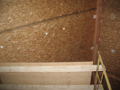
This shot is standing on the concrete slab, looking up past the scaffolding at the roof. The three white circles are where we’ve drilled the ceiling panel are about 3 1/2″ in diameter to give you a sense of scale. Now, the thing with pushing a fish tape through a styrofoam panel is that sometimes it gets hung up – especially when you’ve got a 12′ run in a 7-in-12 roof. Every time it gets hung up, you have to decide if it’s something you can fix by just wiggling around a little or if you have to figure out where it’s hung up and drill a new hole to “unhang” it. Between our top and bottom holes, we had to drill 3 other holes to get the fish tape unhung.
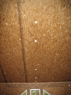
This was shot from the second story walkway and you can see all 5 holes in a neat line. There is about 2′ of 12-3 romex in a yellow sheath hanging from the topmost hole and a line leading from the bottom hole off to the right.
Now, you may be wondering how exactly I was able to work on this? Well, fortunately I was able to borrow some scaffolding from the guys who are building my parent’s house.
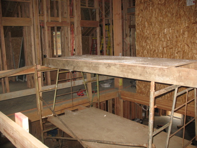
This is shot from the 2nd story and you can see how the upper platform is above the railing for the 2nd story walkway. I spent a good number of hours up there yesterday, wrestling with the drill, the cord, a small ladder to gain a couple extra feet at the tallest point, and my dislike of high places. Fortunately, I’m still here, the wire is all pulled and I won’t have to get back up there until I learn how to install a ceiling fan box in the panel in such a way to support the fan adequately – probably later this week.
Now, there are two rooms that really will only work to wire with furring strips – the two bedrooms with dormers. My dad and I spent additional time yesterday working on that.
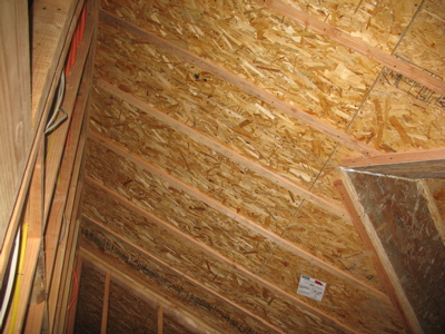
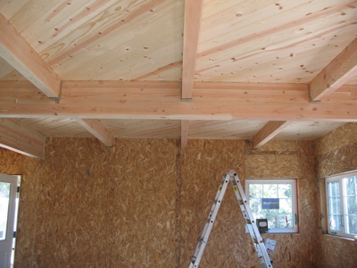
These are 1x4s that my cousin and I ripped in half weeks ago. We spread subfloor glue on one side, and nailed the up. The nails should hold them while the subfloor glue dries and I’ll go back and put a few screws in later just to make triply sure that they hold. I’ll run the wire down center channel where the peak is and the ceiling fan will mount to a block of wood I’m going to anchor into the peak there.
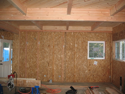
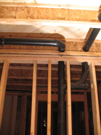
Finally, here’s a shot clearly showing the ramifications of not having an attic space for wiring.
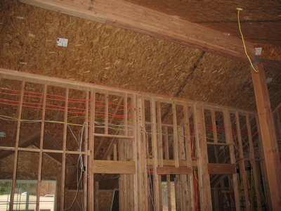
The orange cables are network and comm lines. The white is 14-gauge romex and the yellow is 12-gauge. These walls are not load-bearing – they’re just to delineate the rooms and provide a place to hang drywall.
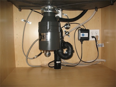 A direct shot of the cabinet under our sink. I was trying to keep everything as clean as possible and keep space for storage. To that end, all of the hoses are run in the back and the waste line is very compact – though only having a single bowl sink helps with that. Since we have a pullout faucet and four water valves, I pegged the faucet supply line up on the left to prevent the pullout from getting hung up on anything.
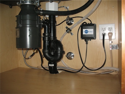 This shot is from further to the right – just another perspective on it. The white box near the top of the picture is our STUDOR® vent. For those of you unfamiliar with it, the black box near the plugs is the controller for our air switch. The dishwasher waste line is pegged to the back wall to keep it stable and prevent it from resting/rubbing on the air switch controller. I used some leftover 7/8″ hose as a buffer between the waste line and the plumbers tape.
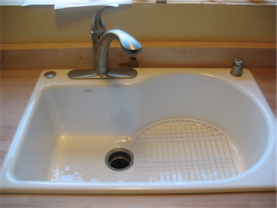 Our sink from above with all the bits and bobs installed. I’m not really happy with the air gap (on the right). It’s got a threaded plastic body and plastic nuts and they keep slipping the thread whenever I jiggle the hoses. I’m going to see if there’s a metal one avail and switch it out. Since our countertops are maple butcher block, I bought some maple planks to fashion the backsplash – that’s what you see here. The counter tops are 25″ deep and the cabinets with drawer/door faces are also 25″ deep. It didn’t look very nice to have the countertops and doors/drawers in the same plane so one of the reasons for going with such a thick backsplash was to push everything out. The backsplash is 1 3/4″ thick and we cut a 1/2″ thick, 3/4″ tall rabbet out of them. This gives us an extra 1 1/4″ of countertop past the cabinets and gives us a lip to hide any inconsistency where the backsplash meets the counter.
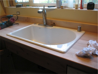 The sink again, from the side so you can see more of the countertop (and a few of my tools).
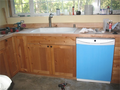 The dishwasher is installed and working. I tested it briefly by starting the cycle and then canceling. Beyond making sure it worked, I also needed to ensure that there were no leaks. No, it’s not really blue – that’s just the protective cover.